Signal inputs
Input Block
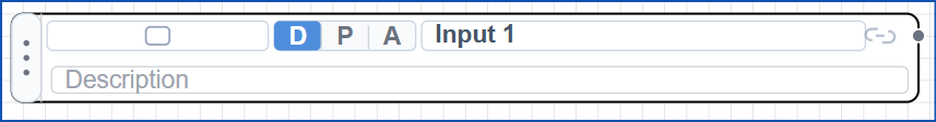
The input block represents an incoming field signal that brings a discrete process condition into the control logic.
Block Library
Control Logic Studio currently lists 38 block entries across six main library section types. Open a section below to browse the available symbols in that category.
The input block represents an incoming field signal that brings a discrete process condition into the control logic.

The mini switch represents a maintained operator or field switch that holds its state until it is changed again.

The pulse switch generates a brief momentary signal so a command can trigger logic without remaining latched on.
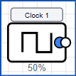
The clock block provides a repeating timed signal that can be used to trigger periodic actions or pace sequence logic.
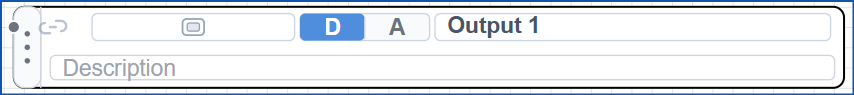
The output block represents a driven logic output used to command an external device or pass an active control state onward.

The light bulb symbol indicates that a circuit state is active and is typically used to show status, run, or alarm conditions.
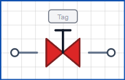
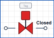
The manual valve symbol represents a hand-operated valve whose process state is set by an operator rather than by a driven output.
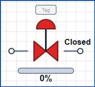
The auto valve symbol represents an actuated valve whose open or closed state is controlled directly by the automation logic.
The control valve symbol represents a modulating final element that adjusts process flow in response to a control signal.
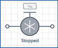
The pump symbol represents a driven process unit that starts or stops to move fluid when the logic issues a run command.
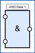
The AND gate only produces an active output when every required input condition is true at the same time.
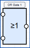
The OR gate turns on when any one of its valid input conditions is true.

The NOT gate inverts the incoming state so a true signal becomes false and a false signal becomes true.
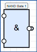
The NAND gate gives an inactive result only when all of its required inputs are true together.
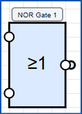
The NOR gate becomes active only when every monitored input remains false.
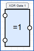
The XOR gate turns on when its compared inputs differ, making it useful for change or mismatch detection.
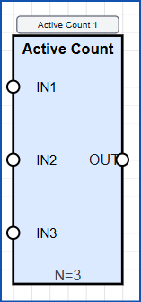
The active count comparator evaluates how many inputs are on and compares that total against a required threshold.

The edge detector produces a short event when it sees a state transition rather than a maintained condition.
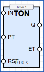
The timer block delays or measures an action over time so logic can react after a configured interval.
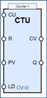
The counter block tracks events or pulses and changes state once the configured count condition is met.
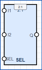
The digital two-to-one selector routes one of two discrete input paths through to the output based on a select condition.
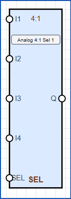
The analogue four-to-one selector chooses one of four analogue values and passes the selected signal onward.
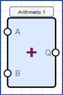
The arithmetic block performs numerical operations so control logic can calculate derived process values.
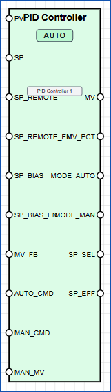
The PID controller continuously adjusts its output to reduce the error between a measured value and a target setpoint.
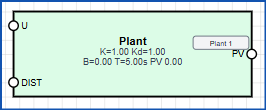
The plant delay block represents lag between an applied control action and the visible response from the process.
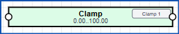
The clamp block prevents a signal from moving above or below defined limits.
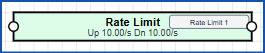
The rate limit block restricts how quickly a value can rise or fall to smooth aggressive changes.
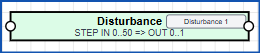
The disturbance block injects an external upset into the model so the control strategy can be tested against changing conditions.
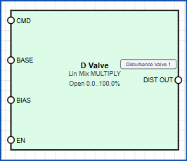
The disturbance valve block models a valve-driven upset so flow changes can be introduced into the process response.
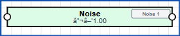
The noise block adds random variation to a signal so measurements and control can be tested under less ideal conditions.
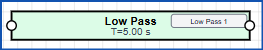
The low pass block smooths a signal by filtering out rapid changes and high-frequency noise.
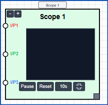
The error scope block visualises how error changes over time so tuning and dynamic behaviour can be reviewed.
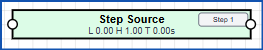
The step block applies a sudden change to a signal so the process response can be examined.
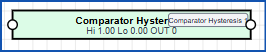
The hysteresis comparator changes state using separated switching thresholds so noisy signals do not chatter.
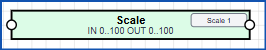
The scale block converts one numerical range into another so raw values can be mapped into engineering units.
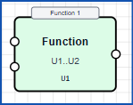
The function block applies a defined mathematical or logical transformation to produce a calculated output.
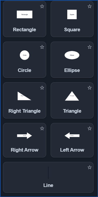
The basic shapes image shows the general-purpose graphic building blocks used to assemble custom layouts, panels, and screen elements.